
 |
| Photo by D. Reifsnider |
The fuselage of the Senior Telemaster has sides that are built up with one directly on top of the other. You start by gluing up the forward sides and pinning them down to a flat wax paper covered surface until the glue has dried.

Once the forward sections are dry, you align them opposite of each other and mark bulkhead and engine mount positions. Then you add the stringers to one side.

The other side is then built over the first so that both sides match.


With both sides of the fuselage built, it was time to add the bulkheads and horizontal stringers. At this point I decided to make a magnetic building board. This was a great time saver and and gave me a fuselage that was perfectly square. My magnetic board consisted of a 20"x 60" piece of 18 gauge galvanized sheet metal that I had the local HVAC shop cut for me. Then I set about making 90 degree magnetic fixtures from various items. I cut some 90 degree triangles from 1/4" basswood, used a few 90 degree builders squares I bought at harbor freight, as well as a couple of other wood fixtures I had around the shop. I epoxied 1-1/2" strips of sheet metal to the bottoms of all my triangle fixtures and placed 3/4" ceramic magnets to the bottoms and secured them with packaging tape. This worked well and I had plenty of holding power with these small magnets. On a few of wooden fixtures I put screws into the 45 degree edges so that I could but them up to the fuselage sides and then strap rubber bands across them to give downward pressure.


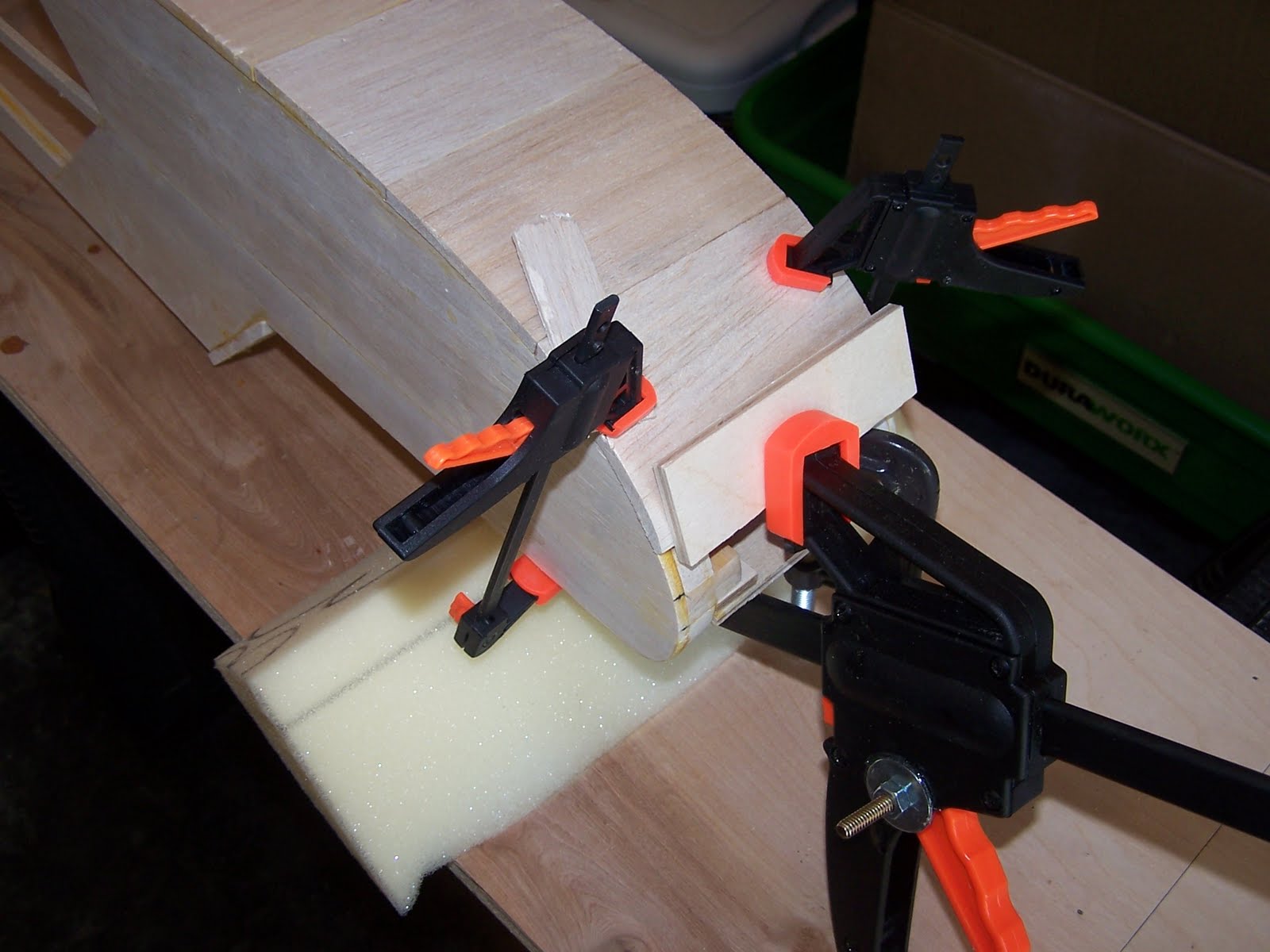
Once I had all my fixtures together, I placed the sheet metal over my building table with the fuselage plan view on top and a piece of wax paper over that. I was then able to clamp the fuselage sides and bulkheads together using my magnetic fixtures to hold everything while I cut the horizontal stringers to size. Once I had all my pieces cut, it was simply a matter of going back and gluing each item while holding everything together with my magnetic fixtures, rubber bands and a few spring clamps. One note here, I made bulkhead #2 out of 1/4" plywood instead of balsa as it would be holding the forward wing with the G10 wing doubler that was fabricated to secure the wing, versus rubber bands that the plans called for. If you want touse this method to secure your wing, be sure to cut the slot in the bulkhead to accept the doubler prior to installing the bulkhead.


Once the sides and bulkheads were glued up, I added the landing gear plate and bottom stringer. This was done prior to removing the fuselage from the building board.

5/8" triangle reinforcement blocks were added to bulkheads #1 and #2 as well as inside the fuselage securing the landing gear plate.


Below you see the addition of the fuel compartment bottom sheeting.
Mounting landing gear.


Fitting the engine bearing plate.

Fuel compartment cover.


A custom fabricated fuselage to wing strut bracket was installed just aft of landing gear. An additional piece of 1/4" plywood was placed on the bottom of the fuselage to support the aluminum bracket.


Installation of the tail wheel using a Sullivan bracket.


Installed switch and charge jack.


Fuel proofing the engine and fuel tank compartments prior to covering the fuselage.


Control rod installation.


Servo tray with electronics ready to be mounted.

Bare bones completed, ready for covering.

No comments:
Post a Comment