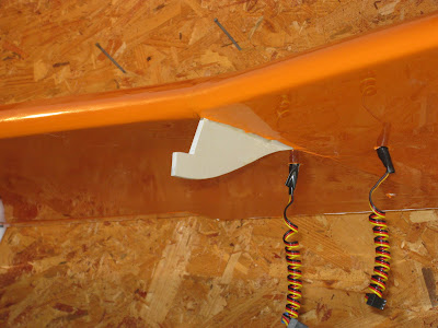
The plans for the Senior Telemaster call for the wing to be mounted to the fuselage using rubber bands. While this method has been used successfully on many models, I wanted a more secure method of mounting the wing on my Telemaster.
If you have been following this series you will have noticed that during the wing build, I installed what I call a "wing doubler". This is an extra rib in the center of the wing that has an extended tab on the front that is meant to slide into a slot in the number two bulkhead which I made from 1/4" plywood. This secures the leading edge of the wing. I decided to make this doubler out of an epoxy composite material called G10. While a cheaper alternative would have been plywood, I wanted something I knew would not bend or break. G10 definitely fills the bill. I was able to easily cut it with a jig saw and ceramic tile blade. Do take caution if you decide to use this material as The fibers created when cutting or grinding are hazardous. You diffidently want to wear a respirator when working with G10.
To secure the rear of the wing, I chose to use bolts that go through the top of the wing, down into the fuselage and into a plywood bracket where they meet a blind nut. I could have run the bolts through the trailing edge balsa and then into a corner bracket, but I wanted the bolts to be gripping on something more substantial. For this I fabricated an aluminum angle piece about 5" long that goes over top of of the rear portion of the wing including the aft section of the doubler and rear wing spar so that these items become integral to the design and would have to actually break for the bolts to pull through. I can tell you from the strength of the G10 alone, that's not going to happen. I'm sure the top of the fuselage would break and pull out before this wing section would.
Below is the aluminum reinforcement piece that was added to the center section of the wing to disperse the pressure of the wing mounting bolts.
In the photo below you can see the plywood bracket that the wing bolts screw into. Instead of gluing this piece into place I installed plywood ears that rise vertically along the sides of the fuselage. A bolt on each side then secures these risers to the top fuselage stringers. This allows the bracket to be unbolted and slide forward if access to the servo tray below is needed. You also see a plywood battery tray that was added to the center of the bracket. This tray has velcro and a strap to hold the receiver battery in place. The battery was placed here as I needed to shift the CG aft due to the weight of the OS 91 FS Engine.
Below you see here the two 1/4" holes were drilled thru the covering and aluminum reinforcement piece on top of the wing.
 |
| Wing Installed and Bolted Down |


No comments:
Post a Comment