Showing posts with label Senior Telemaster. Show all posts

Thursday, August 4, 2011

Senior Telemaster Build, Power and Fuel ( Part Six)

Photo by D. Reifsnider

In part six and the last in our series on building the Senior Telemaster, I'll briefly go over the engine and fuel system that I have used in this plane. For a power plant, I chose the O.S. 91 FS Surpass II. With it being a four stroke, it's a little heaver than what the designer had intended, but still a tried and proven engine for this plane.

SPECIFICATIONS
Stock Number: OSMG0890
Displacement: 0.912 cu in (14.95 cc)
Bore: 1.091 in (27.7 mm)
Stroke: 0.976 in (24.8 mm)
Practical rpm: 2,000-12,000
Output: 1.6 hp @ 11,000 rpm
Weight w/muffler & manifold: 23.9 oz. (678 g)
Weight w/o muffler & manifold: 22.2 oz. (630 g)
Recommended Props: Stunt: 11x10, 11x11, 12x9.5, 12x10, 12x11; Scale: 13.5x8, 14x7, 15x6, 16x6, 12x8 3-blade, 12.5x7 3-blade

I chose to run a Master Airscrew 15x6 K Series G/F Nylon Propeller. The fuel tank is a Sullivan Slant Tank 12 oz. that is surrounded by foam rubber so that it sets at the top of the fuel tank compartment.
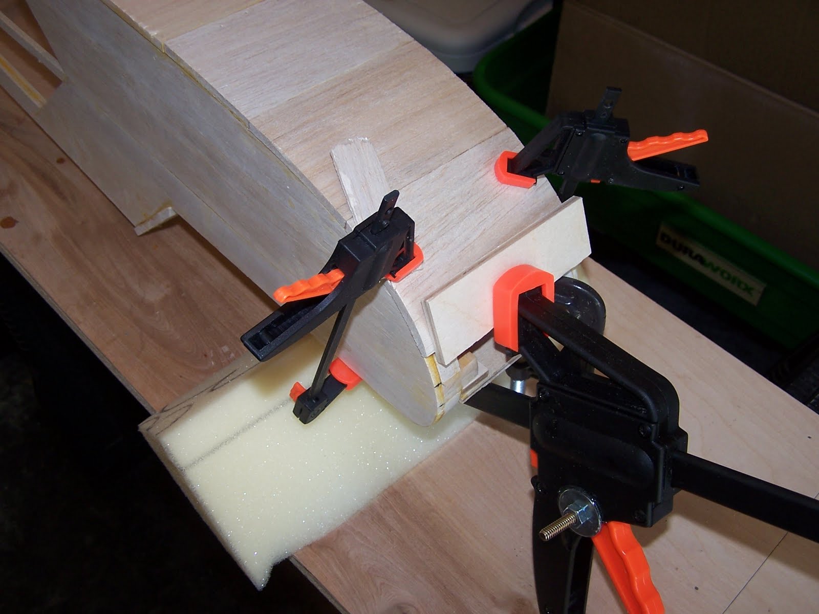
Fuel Compartment

Silicone fuel tubing is routed through the firewall with the supply line being equipped with a Great Planes Ultra Precision Fuel Filter. Homemade barbs were added to the copper fuel lines exiting the tank by wrapping the ends with fine copper sire and then apply a bead of solder over the wire. All internal lines were then secured with Great Planes wire fuel line clamps.

The throttle linkage consists of a Sullivan Gold-N-Rod from the Hitec HS-485HB servo out through the firewall where I used a Du-Bro # 665 4-Stroke Throttle linkage system for connection to the carb. The Du-Bro linkage was needed as the carb on the OS is rear mounted and sets very close the the firewall and does not leave enough room to mount the linkage directly.


Installed Throttle Linkage


I hope you have enjoyed this article as much as I enjoyed building this classic RC airplane. To close it out, I'll leave you with a video of some engine testing that was done prior to getting this lady airborne.


  1. Part One, Wing
  2. Part Two, Tail Feathers
  3. Part Three, Fuselage
  4. Part Four, Wing Struts
  5. Part Five, Wing Attachment
  6. Part Six, Power and Fuel <-- YOU ARE HERE

Senior Telemaster Build, Wing Attachment (Part Five)


The plans for the Senior Telemaster call for the wing to be mounted to the fuselage using rubber bands. While this method has been used successfully on many models, I wanted a more secure method of mounting the wing on my Telemaster.

If you have been following this series you will have noticed that during the wing build, I installed what I call a "wing doubler". This is an extra rib in the center of the wing that has an extended tab on the front that is meant to slide into a slot in the number two bulkhead which I made from 1/4" plywood. This secures the leading edge of the wing. I decided to make this doubler out of an epoxy composite material called G10. While a cheaper alternative would have been plywood, I wanted something I knew would not bend or break. G10 definitely fills the bill. I was able to easily cut it with a jig saw and ceramic tile blade. Do take caution if you decide to use this material as The fibers created when cutting or grinding are hazardous. You diffidently want to wear a respirator when working with G10.


To secure the rear of the wing, I chose to use bolts that go through the top of the wing, down into the fuselage and into a plywood bracket where they meet a blind nut. I could have run the bolts through the trailing edge balsa and then into a corner bracket, but I wanted the bolts to be gripping on something more substantial. For this I fabricated an aluminum angle piece about 5" long that goes over top of of the rear portion of the wing including the aft section of the doubler and rear wing spar so that these items become integral to the design and would have to actually break for the bolts to pull through. I can tell you from the strength of the G10 alone, that's not going to happen. I'm sure the top of the fuselage would break and pull out before this wing section would.


Below is the aluminum reinforcement piece that was added to the center section of the wing to disperse the pressure of the wing mounting bolts.


In the photo below you can see the plywood bracket that the wing bolts screw into. Instead of gluing this piece into place I installed plywood ears that rise vertically along the sides of the fuselage. A bolt on each side then secures these risers to the top fuselage stringers. This allows the bracket to be unbolted and slide forward if access to the servo tray below is needed. You also see a plywood battery tray that was added to the center of the bracket. This tray has velcro and a strap to hold the receiver battery in place. The battery was placed here as I needed to shift the CG aft due to the weight of the OS 91 FS Engine.


Below you see here the two 1/4" holes were drilled thru the covering and aluminum reinforcement piece on top of the wing.

Wing Installed and Bolted Down

  1. Part One, Wing
  2. Part Two, Tail Feathers
  3. Part Three, Fuselage
  4. Part Four, Wing Struts
  5. Part Five, Wing Attachment <-- YOU ARE HERE
  6. Part Six, Power and Fuel

Wednesday, August 3, 2011

Senior Telemaster Build, Wing Struts, (Part Four)

Senior Telemaster photo by Dennis Reifsnider
Photo by D. Reifsnider


In this, the fourth part of our series on building the Senior Telemaster, I'm going to go over construction of the wings struts. While the original plans don't call for them, I decided to add them as a safety measure since I was using an experimental wing mounting system. Also, I  think they look cool. The strut mounting required that I fabricate a bracket for attaching the strut at both the wing and fuselage. Below you will see the bracket that was made for the wing.


The wooden hardwood block was glued in between the upper and lower spars at so that the bracket hung down at the 9th outboard rib. Unfortunately I failed to get a photo of it prior to covering, but below is an illustrated drawing of it's placement.


The photo below shows the finished bracket exiting the covering. Using 1/4" square balsa, I boxed in around the bracket so the covering would have an edge to adhere to. After the wing was covered, I put a bead of epoxyy around the bracket to create a fuel proof seal.


Now for the strut attachment on the fuselage. Starting with 5/8"x 3/16' stock and a Dremel Tool, I fabricated an aluminum bracket that spans the entire width of the fuselage and is fashioned so that the aluminum strut tubes slide over each end. The bracket is fastened to the bottom of the fuselage with a couple of socket head screws that go into blind nuts installed in the plywood fuselage support aft of the landing gear plate. The strut tube is fastened to the bracket with a cotter pin.

Strut bracket attachment to bottom of fuselage


As for the struts themselves, I used 5/8" K&S aluminum streamline tubing. In order to give them some added strength, I ran a piece of 3/16"x3/8" balsa inside the length of the tube. I then fabricated an end piece for attaching the tube to the bracket at the wing. The piece was fabricated from brass bar stock and 4-40 threaded rod that was bent into an "L" shape and soldered to the bar stock. A ball link was then attached to the threaded rod.


The above piece was then secured into the end of the strut tubing using J-B Weld liquid steel epoxy resin.


The finished struts are then attached to the wing with a bolt through the ball link and with a cotter key though a hole drilled the tube at the other end.


  1. Part One, Wing
  2. Part Two, Tail Feathers
  3. Part Three, Fuselage
  4. Part Four, Wing Struts <-- YOU ARE HERE
  5. Part Five, Wing Attachment
  6. Part Six, Power and Fuel

Tuesday, August 2, 2011

Senior Telemaster Build, Fuselage (Part 3)

Senior Telemaster Side View
Photo by D. Reifsnider

The fuselage of the Senior Telemaster has sides that are built up with one directly on top of the other. You start by gluing up the forward sides and pinning them down to a flat wax paper covered surface until the glue has dried.


Once the forward sections are dry, you align them opposite of each other and mark bulkhead and engine mount positions. Then you add the stringers to one side.


The other side is then built over the first so that both sides match.


With both sides of the fuselage built, it was time to add the bulkheads and horizontal stringers. At this point I decided to make a magnetic building board. This was a great time saver and and gave me a fuselage that was perfectly square. My magnetic board consisted of a 20"x 60" piece of 18 gauge galvanized sheet metal that I had the local HVAC shop cut for me. Then I set about making 90 degree magnetic fixtures from various items. I cut some 90 degree triangles from 1/4" basswood, used a few 90 degree builders squares I bought at harbor freight, as well as a couple of other wood fixtures I had around the shop. I epoxied 1-1/2" strips of sheet metal to the bottoms of all my triangle fixtures and placed 3/4" ceramic magnets to the bottoms and secured them with packaging tape. This worked well and I had plenty of holding power with these small magnets. On a few of wooden fixtures I put screws into the 45 degree edges so that I could but them up to the fuselage sides and then strap rubber bands across them to give downward pressure.


Once I had all my fixtures together, I placed the sheet metal over my building table with the fuselage plan view on top and a piece of wax paper over that. I was then able to clamp the fuselage sides and bulkheads together using my magnetic fixtures to hold everything while I cut the horizontal stringers to size. Once I had all my pieces cut, it was simply a matter of going back and gluing each item while holding everything together with my magnetic fixtures, rubber bands and a few spring clamps. One note here, I made bulkhead #2 out of 1/4" plywood instead of balsa as it would be holding the forward wing with the G10 wing doubler that was fabricated to secure the wing, versus rubber bands that the plans called for. If you want touse this method to secure your wing, be sure to cut the slot in the bulkhead to accept the doubler prior to installing the bulkhead.


Once the sides and bulkheads were glued up, I added the landing gear plate and bottom stringer. This was done prior to removing the fuselage from the building board.


5/8" triangle reinforcement blocks were added to bulkheads #1 and #2 as well as inside the fuselage securing the landing gear plate.


Next was the Installation of the engine compartment doublers and engine mounting rails.


Below you see the addition of the fuel compartment bottom sheeting.


Mounting landing gear.


Fitting the engine bearing plate.


Fuel compartment cover.


A custom fabricated fuselage to wing strut bracket was installed just aft of landing gear. An additional piece of 1/4" plywood was placed on the bottom of the fuselage to support the aluminum bracket.


Installation of the tail wheel using a Sullivan bracket.


Installed switch and charge jack.


Fuel proofing the engine and fuel tank compartments prior to covering the fuselage.


Control rod installation.


Servo tray with electronics ready to be mounted.


Bare bones completed, ready for covering.


  1. Part One, Wing
  2. Part Two, Tail Feathers
  3. Part Three, Fuselage <-- YOU ARE HERE
  4. Part Four, Wing Struts
  5. Part Five, Wing Attachment
  6. Part Six, Power and Fuel