Wednesday, August 31, 2011

Homemade Field Box

This wooden field box is easy to build, inexpensive and is perfect for getting all the stuff you need to start your nitro bird up to the flight line.

It is designed to carry a gallon jug of fuel, Starter with a 12 volt gel cell battery, glo plug igniter, fuel pump and a few hand tools.

All the materials I needed for this project were available at my local home improvement store for under $15.00 not including paint. I had enough material left over to build a second box. I'll be painting mine with some epoxy paint I have around the shop as it will protect the wood from any nitro spills.


Materials:

(1) 1"x10"x6'Pine Board
(1) 1"3"x8' Pine Board
A handful of 1-5/8" sheetrock screws.

Tools Used:

Skill Saw
Jig Saw
Drill & Bits

Consumables:

Sand Paper
Wood Glue

Plans:

Click Image for Larger View


Thursday, August 11, 2011

ParkzoneT-28 Trojan Motor Upgrade

Deciding what motor, prop, ESC and battery combination to use when up-grading your Parkzone T-28 Trojan can be a difficult task.

After much research, here is the equipment I decided to put in mine. While not the cheapest alternative, this setup is simple to install and does not leave any question whether the components are capable of handling the task.

For a power plant I chose E-Flite's Power 10 brushless outrunner motor. Weighing in at 122g (4.3oz) it is not so heavy as to make your T28 a flying brick.  Designed for a current draw of 32A and a maximum burst current of 42A the stock speed control might handle the current draw, again I say "might" but a higher capacity ESC is a much better choice. Even though a 45A speed control would give you adequate head room, I chose to use the Castle Creations Ice 50.


If you go this route you will have to do some soldering. The Ice 50 come with no battery or bullet connectors for the motor. It includes a 5amp switching BEC to power your receiver and servos as well as providing you with extensive data logging capabilities. It can also be used with Castle Creations quick link giving you the ability to program the controller via your computer through a USB port. The only draw back to this great ESC is that it's a little on the heavy side.

One reason for using the Power 10 is it's size. It is a direct replacement for the stock motor. You won't need to shim anything or trim the cowl to install. I have read of users having the stock plastic mount break under the added torque. If you decide to use the stock mount, it would be a good idea to reinforce the 4 standoffs with epoxy as this seems to be where the mount tends to breaks. For my T28, I chose to upgrade to an aluminum mount as sold by Custom RC Parts. They make mounts for just about any motor you might want to put in your T28 as well as other Parkzone airplanes. You will not have any worries with this mount and they include all the hardware necessary for installation.

Now for the selection of a prop and battery. I ran several different prop selections through Electric Motor Calculator to get an idea of what prop would work the best and decided to try a APC 10x7. I did some testing and found that the stock set-up produced 216 watts drawing 20.24 amps. The Power 10 with the 10x7 produced 360 watts at 34 amps. With the new amp draw you will want run at least a 2200mah battery with minimum C rating of 20. I still get a good 8 minute flight with this combination giving the T-28 a marked improvement in speed and vertical thrust.

The only drawback to this combination is that of weight. With the added nose weight it was necessary to cut some of the foam from the bottom of the canopy and move the battery back to get the COG right. I also found it necessary to add a wooden support and velcro strap to secure the 2250mah batteries I was using in this rearward position. Checkout this post for more details on the extended battery tray.


Extended Battery Tray for T28

Having upgraded my Parkzone T-28 Trojan with a Power 10 motor, I found it was quite nose heavy. In order to move the center of gravity back, it was necessary to shift the battery aft to a point that it was no longer comfortably held in place by the stock foam sleeve. Not wanting to see what happens when a battery hits the eject button, I chose to install an extended battery tray.

To construct this tray I started with a piece of basswood 1/8"x 1-1/4" cut so that it fit snugly between the fuselage sides. Roughly four inches long. Then I cut two slots into this piece spaced apart the width of my batteries. I then took a standard 6" velcro battery strap and looped it down, under and back up through the slots in the tray as shown below. Then I mixed up a batch of 5 minute epoxy and glued the tray and strap down directly behind the foam bulkhead. It was also necessary to carve out some of the foam from the bottom of the canopy so the battery could be slide back.


Top View of the Extended Tray


End View of the Tray

Bottom of Canopy Showing Foam Removal
I've had over 100 flights with this extended tray and several crashed and the battery has always remained secured in place. Even if your running a stock set-up and don't need to move the CG back, this extended tray is a great added safety measure to keep your battery secure.

Tags:
T28 Trojan, RC, airplane, Lipo battery,


Wednesday, August 10, 2011

Replacing the Motor and Gearbox in PZ UM P51

The motor and gearbox for Parkzone's Ultra Micro P51 can be easily replaced. If you plan on replacing both the gearbox and motor, you will need part# PKZ3624. The gearbox only is part# PKZ3527 and the motor only is part# PKZ3616. You can find a complete list of replacement parts for this aircraft here.

New Motor, Gearbox, Prop and Spinner From Horizon Hobby

New Motor and Gearbox Ready for Installation
To gain access to the internal components you have to take an Xacto knife and cut along the seam cutting through the decal on each side and along the rear of the top fuselage half.
Fuselage Access

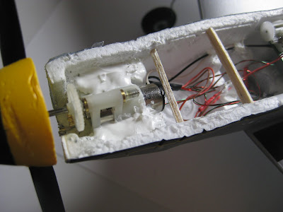
Once you have access to the motor area you again take you Xacto knife and cut along the foam at along the areas shown in red below to separate the caulking used to secure the gearbox in place. You will also need to separate a couple of areas  of caulking that secure the wiring.


Once you have the gearbox, motor and wiring separated from the caulking, you will need to unplug the motor wires from the rear of the receiver. Note that the white wire is inboard and that the plug uses the out board two pins. Be sure to use tweezers to unplug the JST plug. Don't pull on the wires to remove the plug as this can break the wiring to the plug.


Photo shows the two pronged male plug removed from the reciever


Old Motor removed from the fuselage
At this point you will want to plug the new motor in and see that it runs with no problems. If so, lay down a layer of adhesive caulking along the fuselage sides where the gearbox mounts. Press the new gearbox and motor into this layer of caulk. Route motor wire along the side of the fuselage and under receiver circuit board. Plug the wiring into the the receiver and secure the wiring along the side of the fuselage with a couple of dabs of caulking. Also pull the motor wiring under the receiver to one side and secure it with a dab of caulk so that the wires are away from the aileron servo motor gear.


Put a second layer of caulking over top of the gear box flanges Allow the caulking to dry at least 24 hours before starting up the motor or putting any strain on the power system. The additional wires you see in the photos are for the navigaional lights that I added. The balsa cross members are an attempt to reinforce a badly deformed fuselage nose.

All that's left to do is put the fuselage top back on, secure it with a few pieces of Scotch tape and your motor replacement is finished.

Tags:Parkzone P51 Ultra Micro, RC, Radio Control, Airplane, Hobby


Tuesday, August 9, 2011

Fixing Ultra Micro Servo Problem

A problem I came across while flying my Parkzone Ultra Micro P51 RC airplane was that of a failed aileron servo. While flying the servo just locked up and the plane fell from the sky. At first the problem was intermittent, the servo would work and then just stall. Finally it locked up all together and I thought I would have to replace it.

Parkzone Ultra Micro P51 Servo

Spektrum AS2000 Linear Servo

After doing some research, I found that other UM P51 owners had the same problem and fixed it by lubricating the screw assembly of the servo. From experience with RC helicopters, I know that it's not a good Idea to oil plastic parts. It might be a temporary fix, but in the long run, the oil will attract more dirt and cause an even bigger problem.

I found that by taking the end of my Xacto knife and carefully rotating the Screw Gear, I could get the servo to re-center and start to move again. It was still locking up each time I tried moving the ailerons, so I was pretty sure the problem was a small partial of dirt getting caught in the screw assembly and locking up the works. I broke out a blow gun and attached it to my compressor along with a small length of tubing that I attached to the nozzle of the blow gun. I then blasted air into screw assembly on either side of the linear slide all the while using my radio to move the slide back and forth. Each time the servo would lock, I could take the Xacto to the Screw gear and get it going again. After a minute or so of this, I was able to dislodge what ever was causing the problem and the servo has been operating fine ever since. This is not the cure all of servo repair, but is worth a try before going to the expense of replacing your servo.

If you think this might be your problem, but don't have an air compressor, no worry. You can buy a can of compressed air at your local office supply store. Typically sold for cleaning computer components, they come with a little spray tube nozzle that will work perfectly for cleaning your servo so you can get back in the air quickly.

Tags: Ultra Micro P51, Radio Control, RC, Airplane

Monday, August 8, 2011

Ultra Micro P51 Nav Lights

A great modification for your Parkzone Ultra Micro P51 is the addition of navigational lights. This lets you fly at dusk, a time of day when the wind typically dies down. If your daring, you could also try night flight. I found a great deal on a L.E.D. kit at S.F. Design Solutions, $15.00 includes shipping . The kit consists of red and green wing-tip nav lights with a blue or white tail light and white landing light. The lights are very easy to install, you just open up the fuselage, plug in the wiring harness, route the wires and your ready to take to the night skies.

The kit includes step by step instructions, but I've included a few photos and a detail of how I routed my wires. If you have never opened up your P51, it requires that you take a Xacto knife and cut through the decals on the fuselage sides and rear of the radio compartment so that you can remove the top to expose the motor, servos and AR6400 receiver.

Kit as received from SF Design Solutions

Below you can see where I have opened the radio compartment and plugged the lights into my receiver to see that they are working properly.

Testing the lights prior to installation
Click Image for Larger View


Pulling the tail LED out of the fuselage thru the vent hole

Tail light installed and anchored with tape

Wires for wing lights exiting thru forward vent hole

Wing wire installed and anchored with tape


Landing Light mounted at bottom of fuselage under the prop

Ready For Takeoff


Thursday, August 4, 2011

Senior Telemaster Build, Power and Fuel ( Part Six)

Photo by D. Reifsnider

In part six and the last in our series on building the Senior Telemaster, I'll briefly go over the engine and fuel system that I have used in this plane. For a power plant, I chose the O.S. 91 FS Surpass II. With it being a four stroke, it's a little heaver than what the designer had intended, but still a tried and proven engine for this plane.

SPECIFICATIONS
Stock Number: OSMG0890
Displacement: 0.912 cu in (14.95 cc)
Bore: 1.091 in (27.7 mm)
Stroke: 0.976 in (24.8 mm)
Practical rpm: 2,000-12,000
Output: 1.6 hp @ 11,000 rpm
Weight w/muffler & manifold: 23.9 oz. (678 g)
Weight w/o muffler & manifold: 22.2 oz. (630 g)
Recommended Props: Stunt: 11x10, 11x11, 12x9.5, 12x10, 12x11; Scale: 13.5x8, 14x7, 15x6, 16x6, 12x8 3-blade, 12.5x7 3-blade

I chose to run a Master Airscrew 15x6 K Series G/F Nylon Propeller. The fuel tank is a Sullivan Slant Tank 12 oz. that is surrounded by foam rubber so that it sets at the top of the fuel tank compartment.

Fuel Compartment

Silicone fuel tubing is routed through the firewall with the supply line being equipped with a Great Planes Ultra Precision Fuel Filter. Homemade barbs were added to the copper fuel lines exiting the tank by wrapping the ends with fine copper sire and then apply a bead of solder over the wire. All internal lines were then secured with Great Planes wire fuel line clamps.

The throttle linkage consists of a Sullivan Gold-N-Rod from the Hitec HS-485HB servo out through the firewall where I used a Du-Bro # 665 4-Stroke Throttle linkage system for connection to the carb. The Du-Bro linkage was needed as the carb on the OS is rear mounted and sets very close the the firewall and does not leave enough room to mount the linkage directly.


Installed Throttle Linkage


I hope you have enjoyed this article as much as I enjoyed building this classic RC airplane. To close it out, I'll leave you with a video of some engine testing that was done prior to getting this lady airborne.


  1. Part One, Wing
  2. Part Two, Tail Feathers
  3. Part Three, Fuselage
  4. Part Four, Wing Struts
  5. Part Five, Wing Attachment
  6. Part Six, Power and Fuel <-- YOU ARE HERE

Senior Telemaster Build, Wing Attachment (Part Five)


The plans for the Senior Telemaster call for the wing to be mounted to the fuselage using rubber bands. While this method has been used successfully on many models, I wanted a more secure method of mounting the wing on my Telemaster.

If you have been following this series you will have noticed that during the wing build, I installed what I call a "wing doubler". This is an extra rib in the center of the wing that has an extended tab on the front that is meant to slide into a slot in the number two bulkhead which I made from 1/4" plywood. This secures the leading edge of the wing. I decided to make this doubler out of an epoxy composite material called G10. While a cheaper alternative would have been plywood, I wanted something I knew would not bend or break. G10 definitely fills the bill. I was able to easily cut it with a jig saw and ceramic tile blade. Do take caution if you decide to use this material as The fibers created when cutting or grinding are hazardous. You diffidently want to wear a respirator when working with G10.


To secure the rear of the wing, I chose to use bolts that go through the top of the wing, down into the fuselage and into a plywood bracket where they meet a blind nut. I could have run the bolts through the trailing edge balsa and then into a corner bracket, but I wanted the bolts to be gripping on something more substantial. For this I fabricated an aluminum angle piece about 5" long that goes over top of of the rear portion of the wing including the aft section of the doubler and rear wing spar so that these items become integral to the design and would have to actually break for the bolts to pull through. I can tell you from the strength of the G10 alone, that's not going to happen. I'm sure the top of the fuselage would break and pull out before this wing section would.


Below is the aluminum reinforcement piece that was added to the center section of the wing to disperse the pressure of the wing mounting bolts.


In the photo below you can see the plywood bracket that the wing bolts screw into. Instead of gluing this piece into place I installed plywood ears that rise vertically along the sides of the fuselage. A bolt on each side then secures these risers to the top fuselage stringers. This allows the bracket to be unbolted and slide forward if access to the servo tray below is needed. You also see a plywood battery tray that was added to the center of the bracket. This tray has velcro and a strap to hold the receiver battery in place. The battery was placed here as I needed to shift the CG aft due to the weight of the OS 91 FS Engine.


Below you see here the two 1/4" holes were drilled thru the covering and aluminum reinforcement piece on top of the wing.

Wing Installed and Bolted Down

  1. Part One, Wing
  2. Part Two, Tail Feathers
  3. Part Three, Fuselage
  4. Part Four, Wing Struts
  5. Part Five, Wing Attachment <-- YOU ARE HERE
  6. Part Six, Power and Fuel

Wednesday, August 3, 2011

Senior Telemaster Build, Wing Struts, (Part Four)

Senior Telemaster photo by Dennis Reifsnider
Photo by D. Reifsnider


In this, the fourth part of our series on building the Senior Telemaster, I'm going to go over construction of the wings struts. While the original plans don't call for them, I decided to add them as a safety measure since I was using an experimental wing mounting system. Also, I  think they look cool. The strut mounting required that I fabricate a bracket for attaching the strut at both the wing and fuselage. Below you will see the bracket that was made for the wing.


The wooden hardwood block was glued in between the upper and lower spars at so that the bracket hung down at the 9th outboard rib. Unfortunately I failed to get a photo of it prior to covering, but below is an illustrated drawing of it's placement.


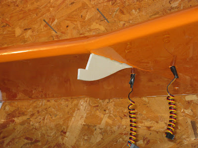
The photo below shows the finished bracket exiting the covering. Using 1/4" square balsa, I boxed in around the bracket so the covering would have an edge to adhere to. After the wing was covered, I put a bead of epoxyy around the bracket to create a fuel proof seal.


Now for the strut attachment on the fuselage. Starting with 5/8"x 3/16' stock and a Dremel Tool, I fabricated an aluminum bracket that spans the entire width of the fuselage and is fashioned so that the aluminum strut tubes slide over each end. The bracket is fastened to the bottom of the fuselage with a couple of socket head screws that go into blind nuts installed in the plywood fuselage support aft of the landing gear plate. The strut tube is fastened to the bracket with a cotter pin.

Strut bracket attachment to bottom of fuselage


As for the struts themselves, I used 5/8" K&S aluminum streamline tubing. In order to give them some added strength, I ran a piece of 3/16"x3/8" balsa inside the length of the tube. I then fabricated an end piece for attaching the tube to the bracket at the wing. The piece was fabricated from brass bar stock and 4-40 threaded rod that was bent into an "L" shape and soldered to the bar stock. A ball link was then attached to the threaded rod.


The above piece was then secured into the end of the strut tubing using J-B Weld liquid steel epoxy resin.


The finished struts are then attached to the wing with a bolt through the ball link and with a cotter key though a hole drilled the tube at the other end.


  1. Part One, Wing
  2. Part Two, Tail Feathers
  3. Part Three, Fuselage
  4. Part Four, Wing Struts <-- YOU ARE HERE
  5. Part Five, Wing Attachment
  6. Part Six, Power and Fuel